Final Project 1: Image Quilting
Introduction
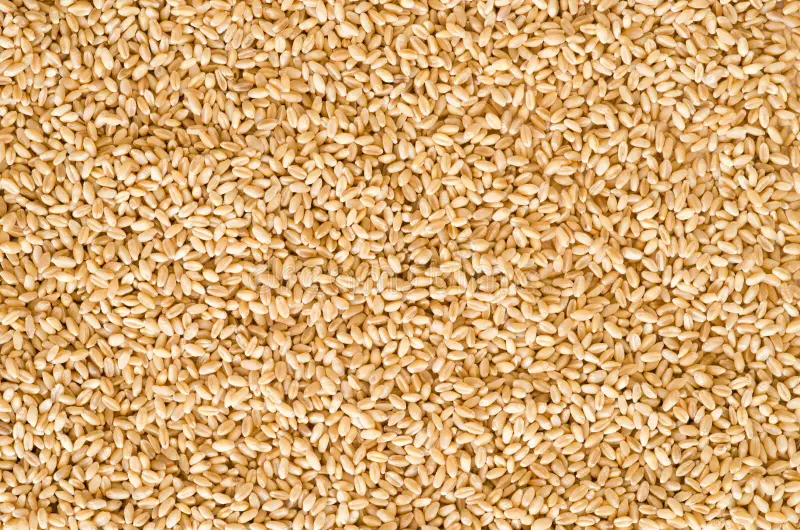
The goal of this assignment is to implement the image quilting algorithm for texture synthesis and transfer, described in this SIGGRAPH 2001 paper by Efros and Freeman. Texture synthesis is the creation of a larger texture image from a small sample. Texture transfer is giving an object the appearance of having the same texture as a sample while preserving its basic shape.
Randomly Sampled Textures
Approach
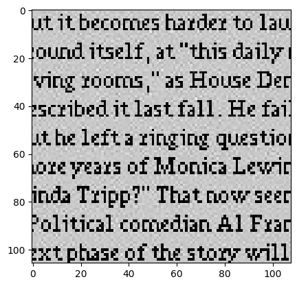
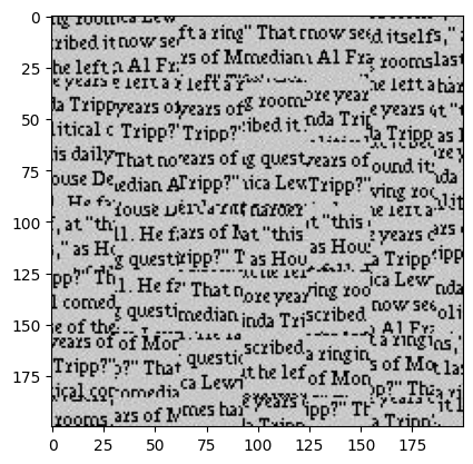
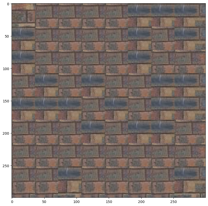
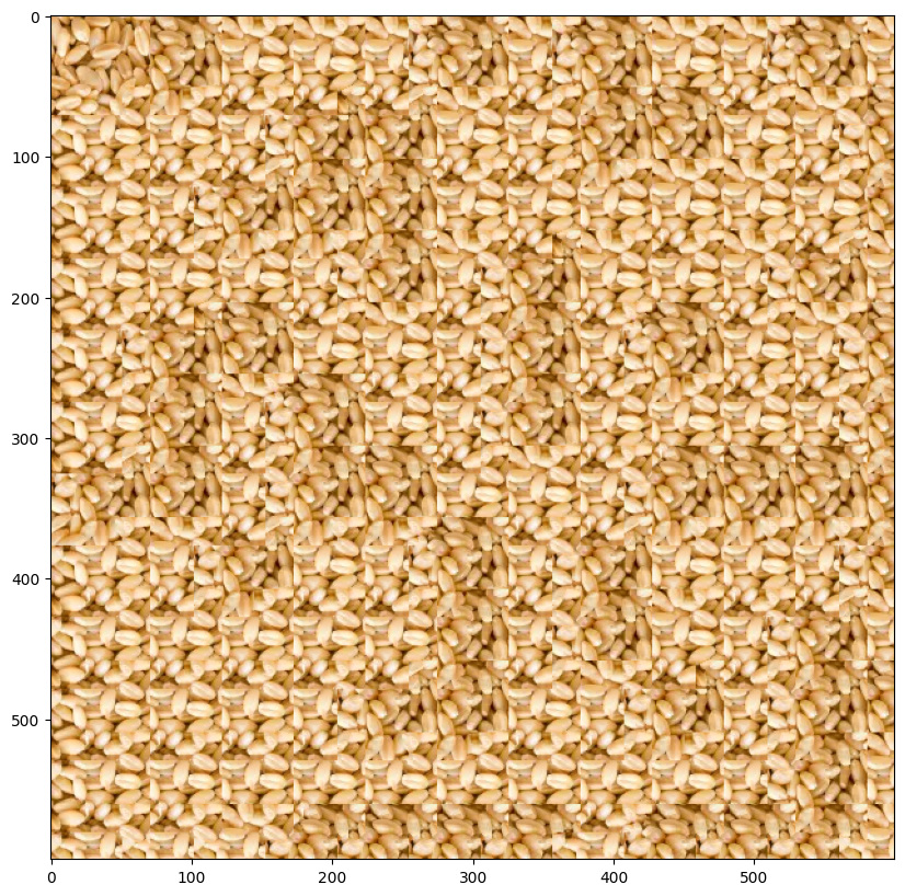
This is the most basic method that creates a larger output image by randomly sampling square patches from an input sample image. It arranges these patches starting from the upper-left corner and tiles them across the output image.
In the below image the parameters used were: patch_size = 31, output_size = (300,300)
Results
Overlapping patches
Approach
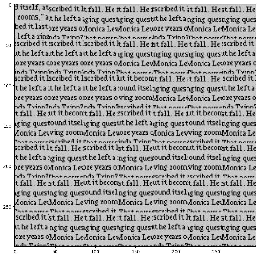
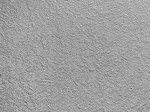
This method constructs a larger output image by sampling square patches from an input image, ensuring that each patch overlaps with existing ones to create a more seamless texture. The process begins by placing a random patch in the upper-left corner. Subsequent patches are chosen based on overlapping regions, using the sum of squared differences (SSD) to evaluate the cost of each potential patch.
SSD Cost Equation:
ssd_cost = ((M * T)**2).sum() - 2 * cv2.filter2D(I, ddepth=-1, kernel=M * T) + cv2.filter2D(I**2, ddepth=-1, kernel=M)
In the below image the parameters used were:
Image1 patch_size = 53, output_size = (300,300), overlap_size = 10, tol = 3
Image2: patch_size = 51, output_size = (300,300), overlap_size = 5, tol = 3
Results

Seam Finding
Approach
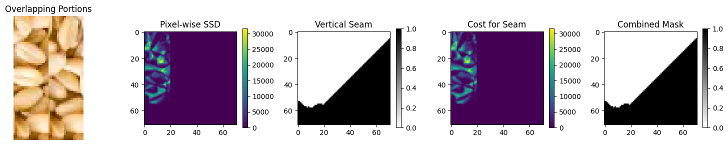
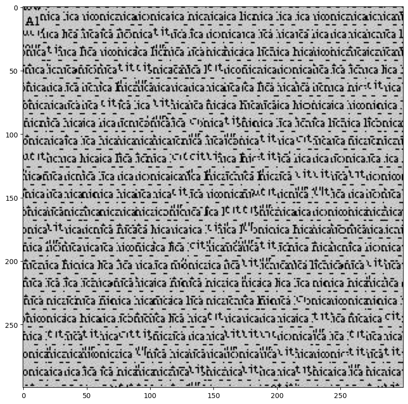
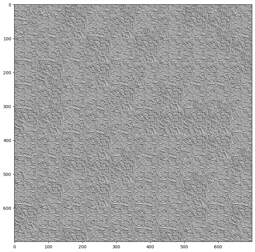
Now we implement the Seam Finding method that aims to remove edge artifacts by finding the best seam (path) to blend overlapping regions between patches. It calculates the cost of seams based on the squared differences between the overlapping areas of the output image and the new patch. Horizontal seams are found using the cut function, while vertical seams are handled by transposing the patch.
For a single patch, here are the the two overlapping portions, pixelwise SSD cost, vertical seam and combination mask.
In the below image the parameters used were:
Image1 patch_size = 19, output_size = (300,300), overlap_size = 5, tol = 8
Image2: patch_size = 101, output_size = (700,700), overlap_size = 30, tol = 3
Image3: patch_size = 71, output_size = (600,600), overlap_size = 20, tol = 5
Results
Texture Transfer
Approach
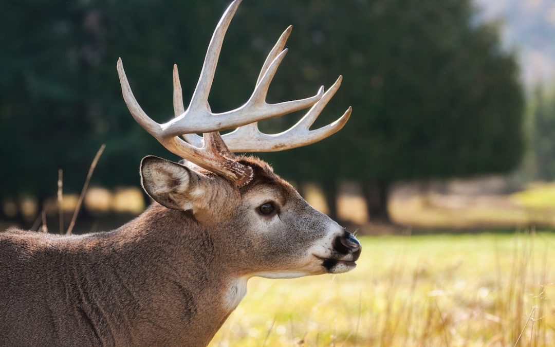
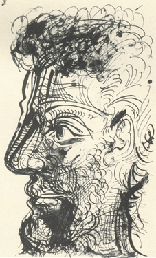
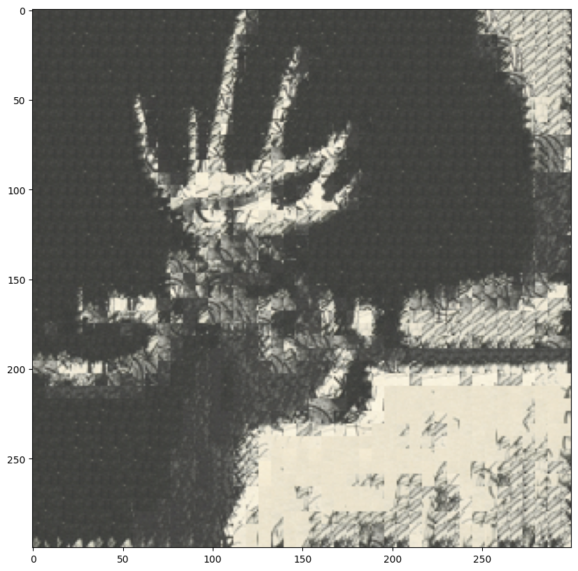
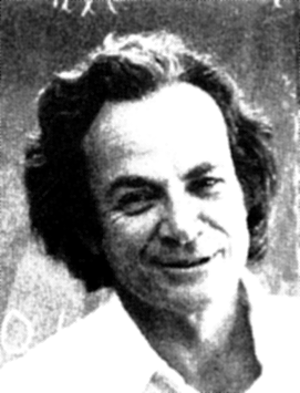
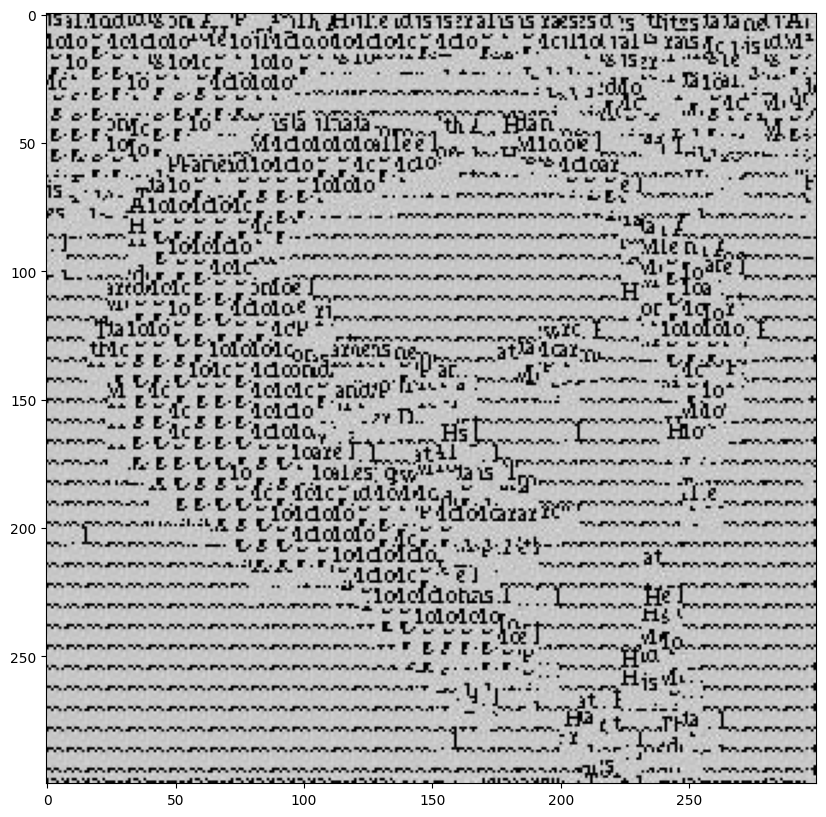
Now finally we implement the texture_transfer function generates a texture guided by a target image. It builds on quilt_cut but adds an extra cost term to account for the difference between the sampled patch and the target image at the corresponding location. This ensures that the texture aligns with the target's structure while maintaining the texture's appearance.
Texture transfer extends Quilt Cut by introducing an additional constraint, called SSD_transfer, which calculates the sum of squared differences (SSD) between the corresponding patch in the target image and the entire sample image. While Quilt Cut only considers SSD_overlap, which measures the SSD between the overlapping region of the output image and the sample image, texture transfer combines both constraints.
The combined SSD matrix is computed as:
α * SSD_overlap + (1 - α) * SSD_transfer
Here, α controls the balance between texture consistency and alignment with the target image. This matrix is then used to select the best matching patch.
The parameters were
Image1 patch_size = 13, overlap_size = 6, tol = 2, alpha=0.65
Image2: patch_size = 17, overlap_size = 7, tol = 3, alpha=0.7
Results

Acknowledgements
The structure of this page was inspired by a website, and parts of the code for creating the website structure were generated using ChatGPT
Final Project 2: Augmented Reality
Introduction
The goal of this assignment is to implement the augmented reality algorithm for tracking points and augmenting a cube on a planar surface. The cube augmentation is achieved by projecting a 3D cube onto the planar surface using the camera's projection matrix.
Here is the initial video
Points Tracking
Approach
We begin by manually detecting the points, then my algorithm tracks these points across frames using the Lucas-Kanade optical flow method. The optical flow algorithm estimates the motion of each point by comparing the intensity values of the point in the current frame with a small window around it in the next frame.
Results
Cube Augmentation
Approach
The cube augmentation is achieved by projecting a 3D cube onto the planar surface using the camera's projection matrix. The projection matrix is calculating using the point coorespondance between 3D and 2D coordinates.
Results
Acknowledgements
The structure of this page was inspired by a website, and parts of the code for creating the website structure were generated using ChatGPT. Thank you